Bringing up WiFi on bare metal
March 19, 2026
This was my final project for CS140E, Stanford’s bare-metal systems class, the one where you build up from nothing on a Raspberry Pi, no operating system to stand on. I wanted the hardest version of “how does this actually work,” so I went for the radio.
The goal: get a Raspberry Pi Zero W onto WiFi with no operating system. No Linux, no vendor driver, no network stack. Just the chip, the datasheets, and the Linux kernel source to reverse-engineer the parts that aren’t documented. The hardware (a Broadcom/Cypress CYW43438) is documented, but spread across a dozen PDFs; the software interface is proprietary, so most of the work was reading kernel source until the sequence made sense, then watching the hardware finally answer.
Here’s the path, roughly in order.
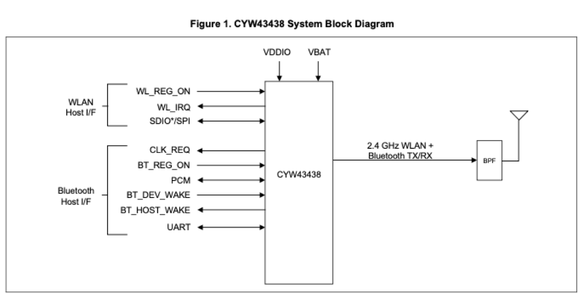
From the CYW43438 datasheet: the chip and its interfaces. Everything below is about waking each of these up in the right order.
A clock the chip can’t live without
The CYW43438 needs a 32.768 kHz clock on its LPO_IN pin or it’s just a dead lump of
silicon. The full path: BCM2835 gpclk2 → GPIO43 → LPO_IN, with the frequency
generated by the BCM2835’s clock-divider math. (Knowing it was GPIO43 at all came from
the Pi Zero W device tree in the kernel.)
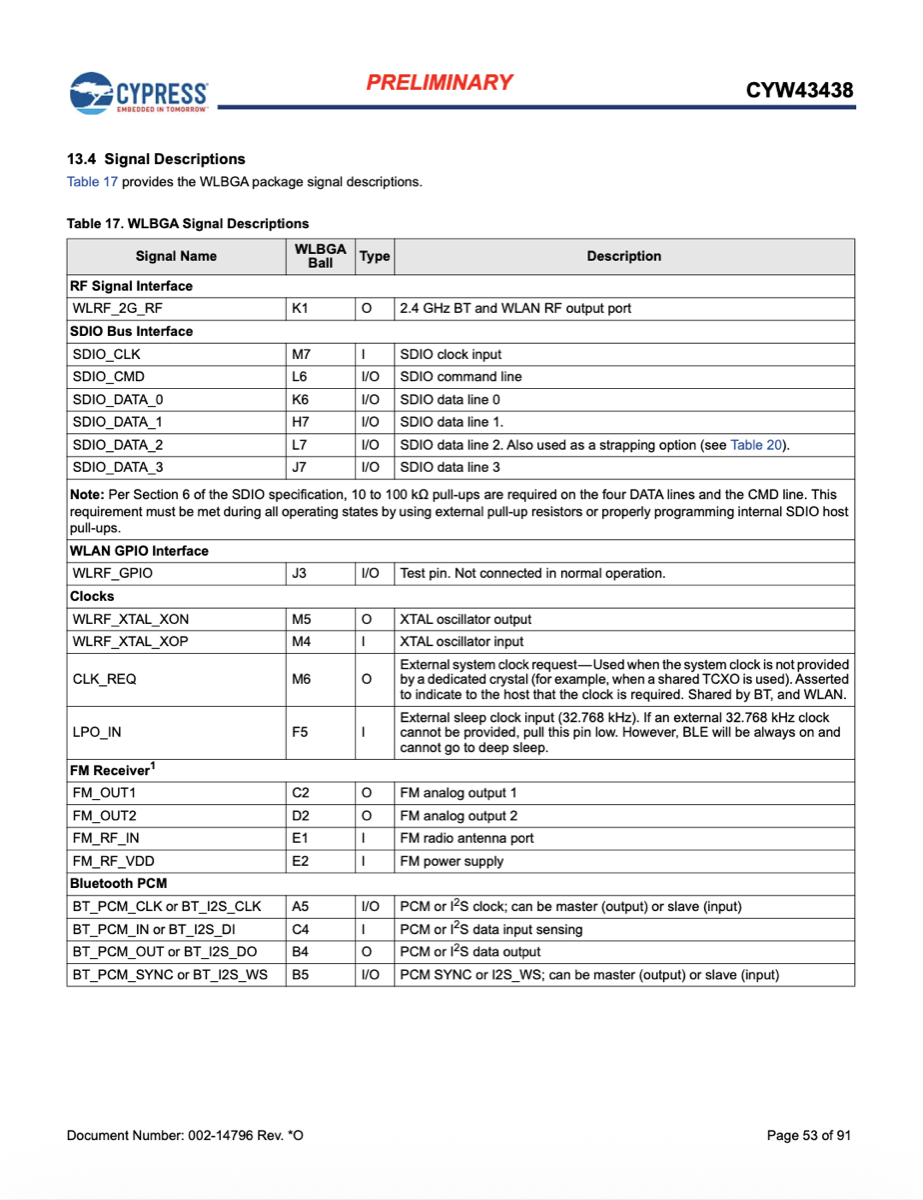
From the datasheet: LPO_IN, the slow 32.768 kHz clock the chip needs before it will do anything.
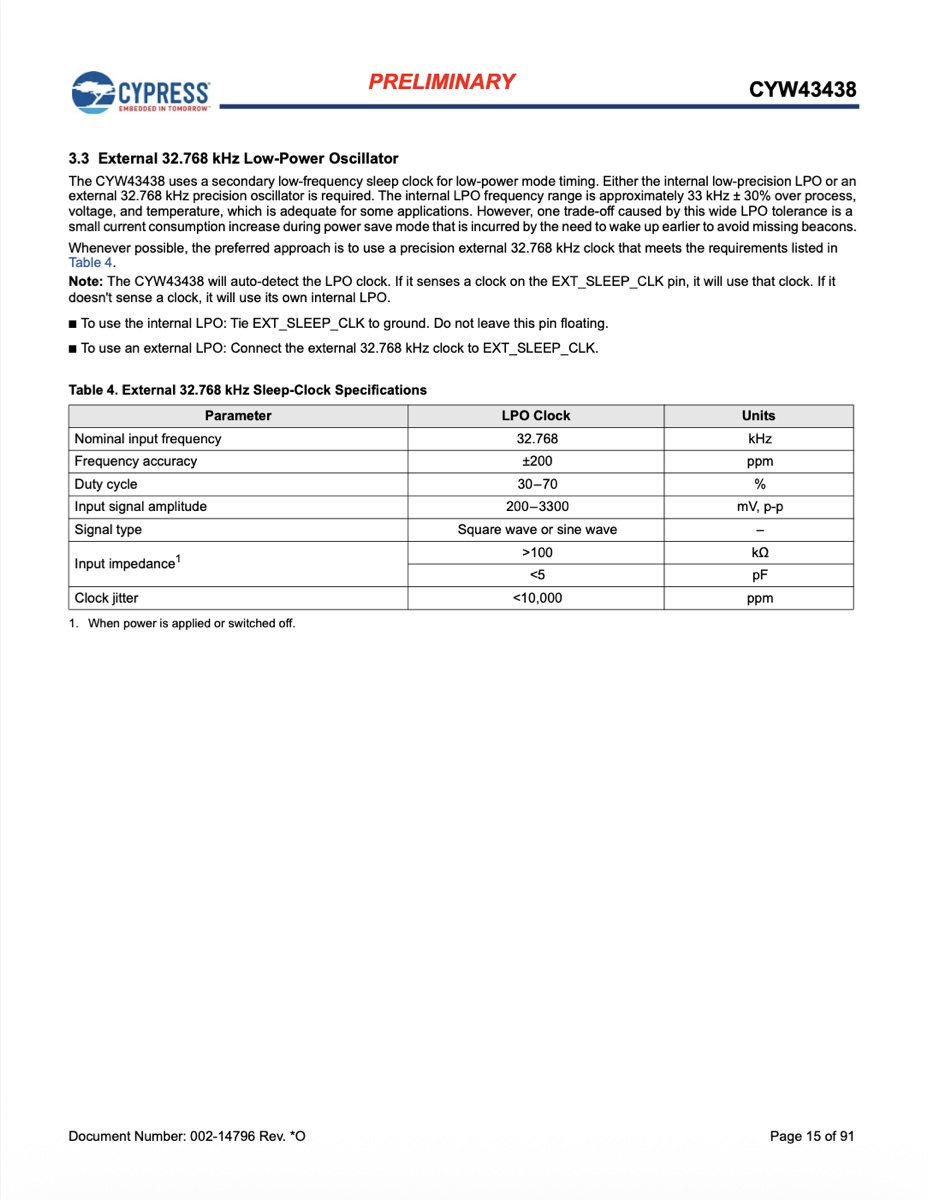
The clock-divider path that turns the Pi’s oscillator into a 32.768 kHz signal on gpclk2.
Powering it on
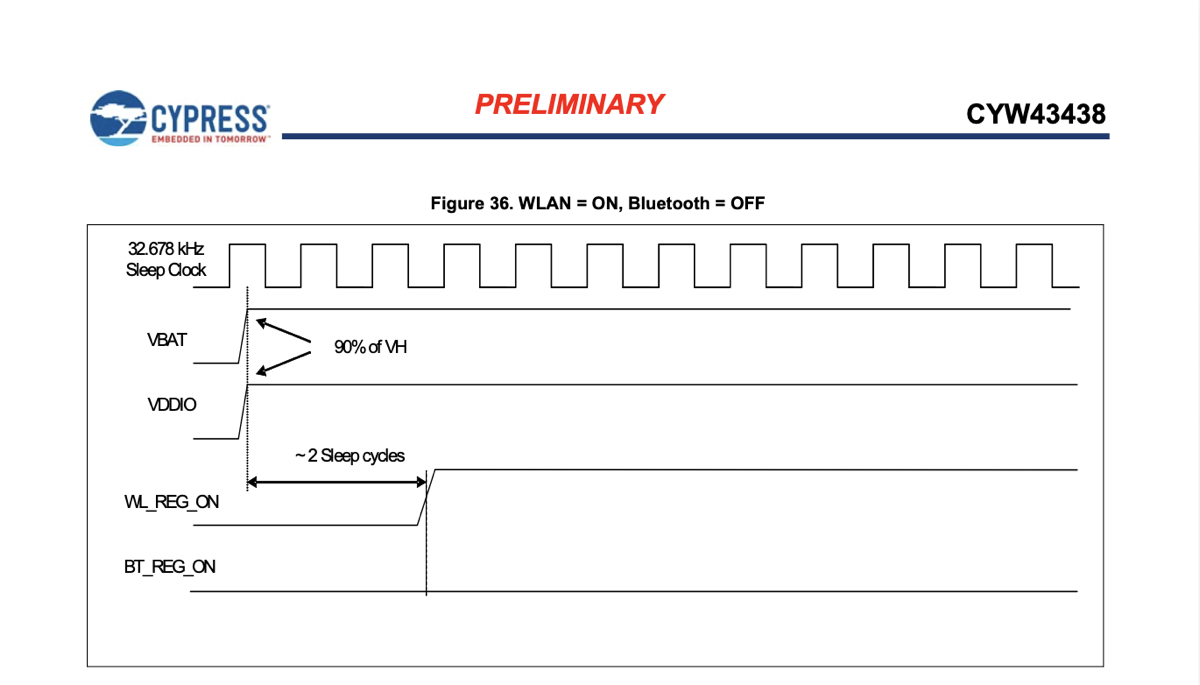
WL_REG_ON has to be driven high or the chip stays off; BT_REG_ON driven low to keep
Bluetooth out of the way. Then configure the SDIO wires (with the pull-ups the datasheet
requires on the command and data lines).
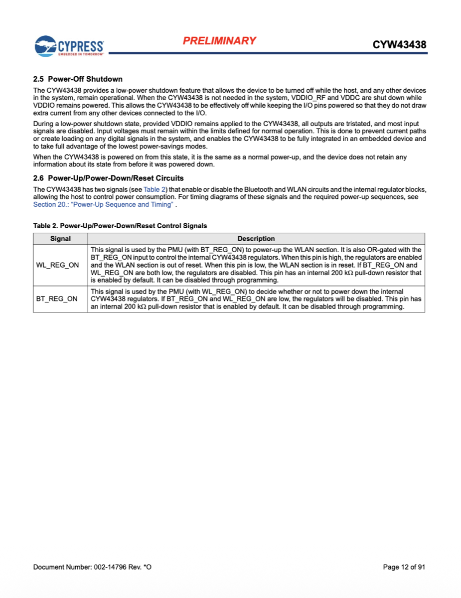
From the datasheet: the regulator-enable line that has to go high to bring the WLAN core out of reset.
Bit-banging SDIO
The BCM2835 has a hardware SD controller, and Linux just hands it the GPIOs in ALT3 and
lets it clock everything. I couldn’t get it to cooperate, so I bit-banged the bus
instead: one function to pulse the clock GPIO, one to read the four data lines at once.
A delay_us(1) between edges is ~1000 ns, thousands of times slower than the minimum
timing, so there was a lot of margin to be wrong in.
From the SDIO spec: the clock, command, and four data lines I had to drive by hand.
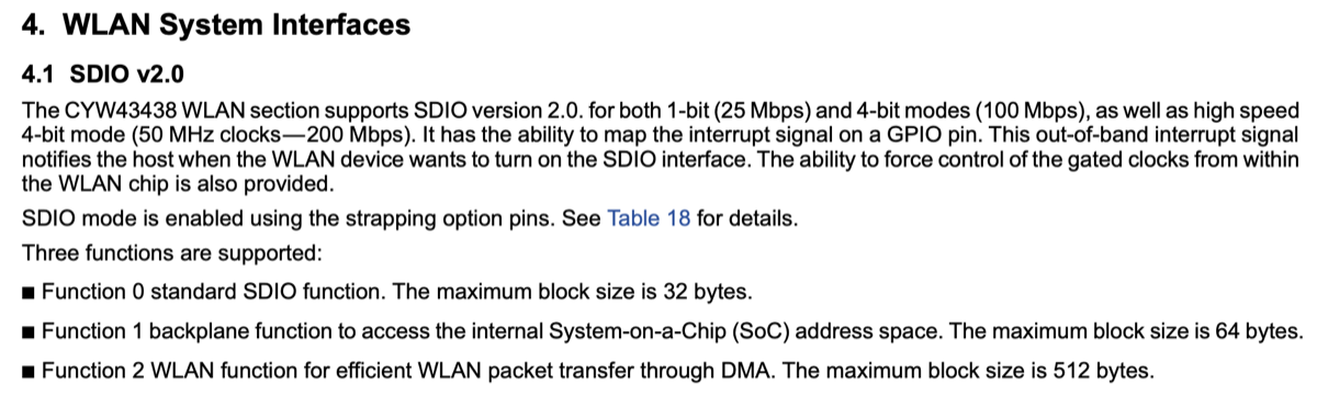
From the spec: SDIO exposes the chip as a set of numbered “functions,” each its own address space.
Into the transfer state, then the backplane
SDIO initialization (CMD5 → CMD3 → CMD7) to get the card into the transfer state, widen the bus, and enable function 1, the “backplane” that exposes the chip’s internal 32-bit address space. First proof of life: reading the chip ID over the backplane.
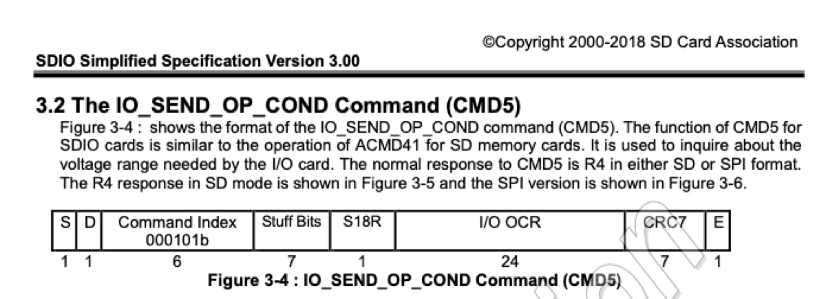
From the spec: CMD5, the first command, which negotiates voltage and starts SDIO initialization.
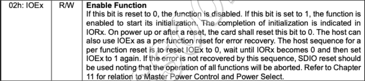
From the spec: the CCCR register where you enable function 1 (the backplane) and wait for it to come ready.
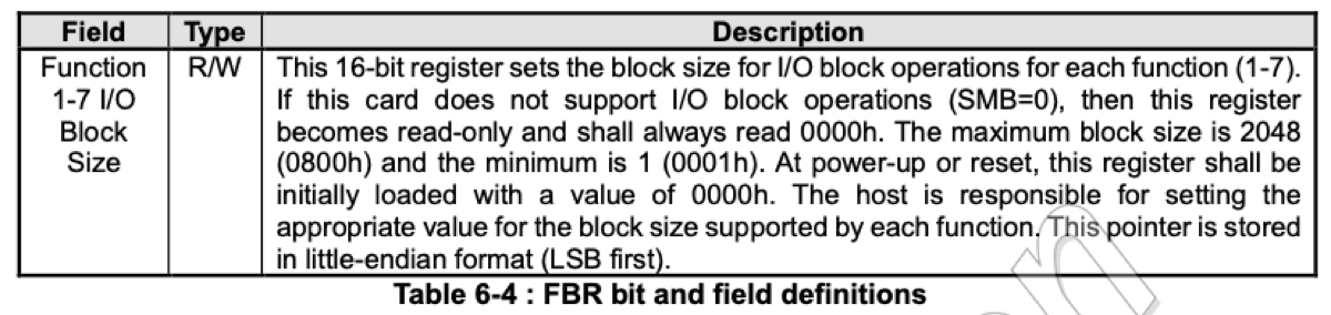
From the spec: setting per-function block sizes so block-mode transfers line up.
Firmware upload
The CYW43438 has its own ARM Cortex-M3. To do anything, you upload firmware into its SRAM: disable the core, sanity-check the SRAM, write the firmware blob 64 bytes at a time over the backplane, write the NVRAM config at the top of SRAM, request a clock, and release the core to run. Then enable function 2 (the WLAN data pipe) and check the mailbox: ready.
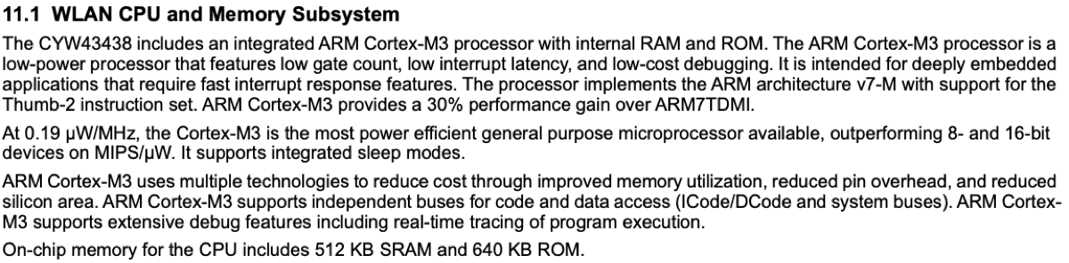
From the datasheet: the chip’s own Cortex-M3 and SRAM, the thing the firmware runs on once you upload it.
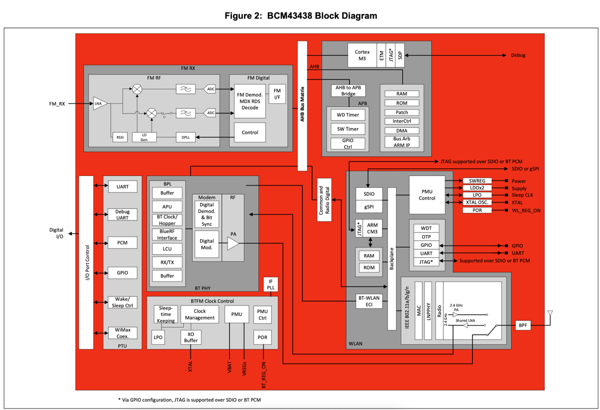
From the datasheet: the WLAN core, with the processor and memory the firmware lives in.
Talking to the firmware (IOCTL / SDPCM)
Once the firmware is running its own CPU, you can’t poke registers anymore. You have to message it. That’s SDPCM + CDC framing over function 2, with channels for control (scan, join, set security), events (scan results, join status), and network traffic.
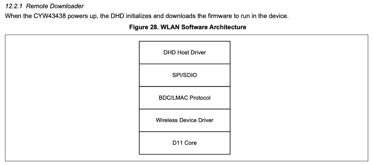
From the datasheet: the firmware’s software stack, what you’re sending messages to once the core is live.
Scanning and joining
An escan request over the control channel, then parse one event per network found. (Fun fact: the Pi Zero W is 2.4 GHz only.) Joining means association plus the WPA2 key exchange, and you’re not done until you’ve seen both the association event and the keys-installed event. Aside: this is why Stanford is nearly impossible: eduroam is WPA2-Enterprise, per-person credentials over a captive portal, a nightmare for a bare-metal driver.
Getting an address, and proving it works
With a clean data path, every Ethernet frame the radio receives lands on the data channel. DHCP is a four-message handshake (discover → offer → request → ack), each one a hand-built Ethernet + IP + UDP + DHCP frame. After that I had an IP, a gateway, and a netmask. To prove the whole path end to end, the Pi sends a UDP broadcast (“hello from bare-metal pi zero w!”) and sits in a loop answering ARP requests and ICMP pings, so other machines can find it and reach it. Built straight from the RFCs (826, 792, 768, 791).
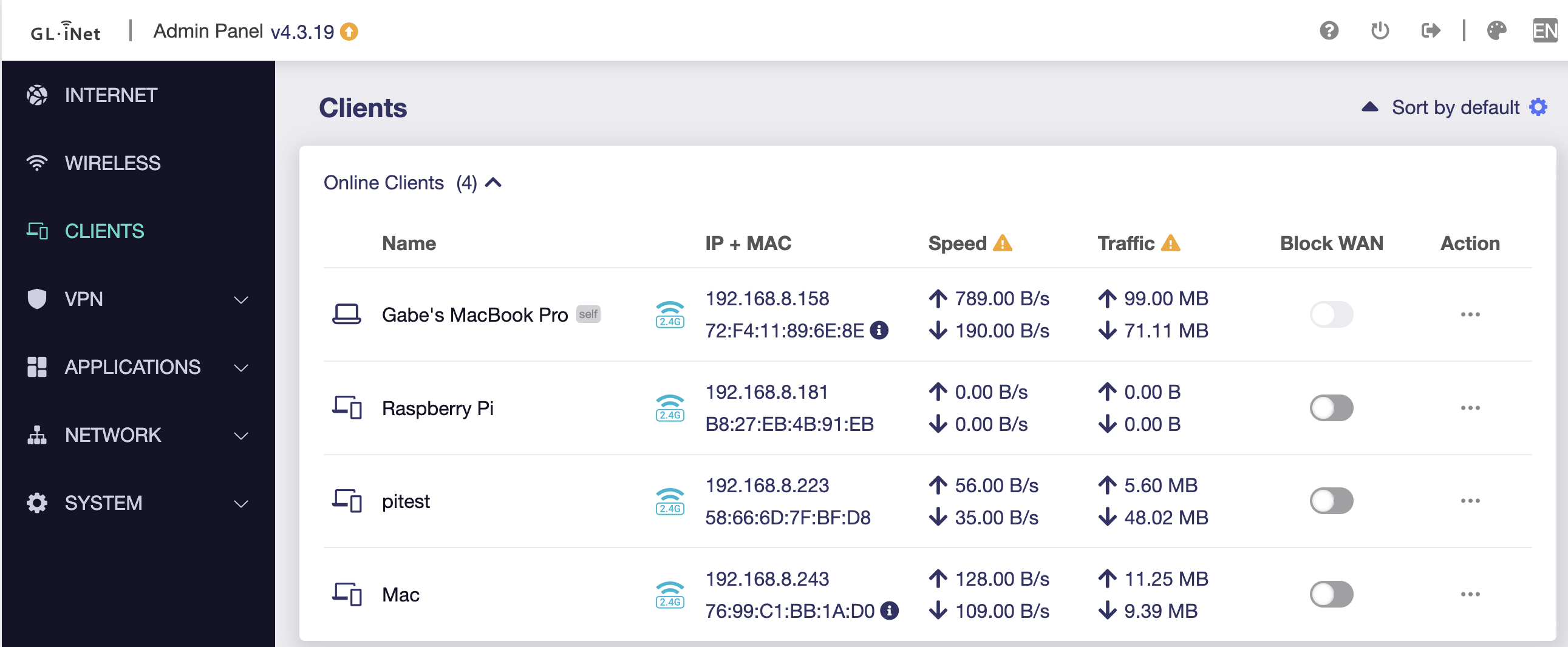
Proof it worked: the bare-metal Pi (192.168.8.181) shows up in the router’s client list, on the network, with its own IP, no operating system anywhere.
Why an LLM
The hardware is documented but scattered: tracing GPIO43 to LPO_IN across the device
tree, the datasheet, and the schematic is tedious but doable. The software interface is
the opposite: proprietary, undocumented, only legible by reading the Linux brcmfmac
driver. An LLM was a real accelerant there, and a lot of the C came from pairing with
one. The engineering was in driving it: deciding the sequence, debugging the silence,
and understanding it well enough to write this down.